Key takeaways
- Turn a cabinet sketch into a checked part list with actual material thickness, clear assumptions and a worked dimensional example.
Turn a cabinet sketch into a cut list by deciding which panels run full length, which fit between them and how the back affects the outside depth. Label each part, calculate its finished dimensions from the actual material thickness, then check the assembled totals. A cut list is a record of parts; it is not yet a sheet layout or a complete construction plan.
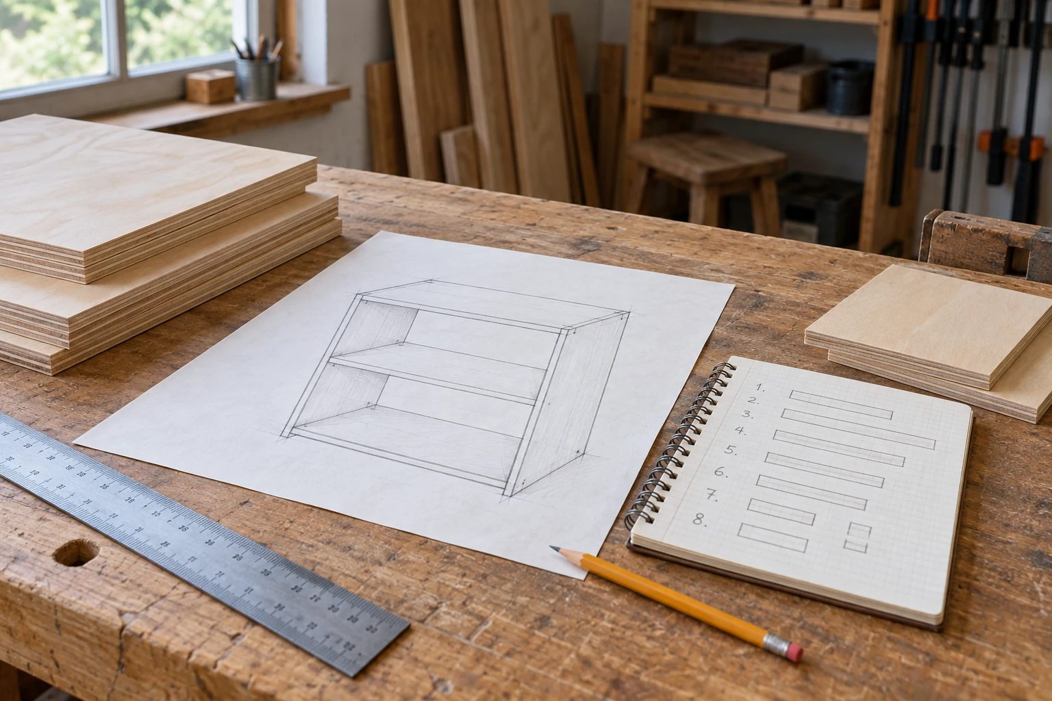
Write the construction assumptions beside the sketch
Draw a front, side and top view. Mark outside width, height and depth, then state whether those dimensions include the back, face frame, doors, feet or countertop. Otherwise two correct-looking calculations can describe different cabinets. Use one unit throughout the working sheet and label it at the top.
Choose which parts overlap. For example, full-height sides with a top and bottom fitted between them require a different top length from a top covering both sides. Draw panel thickness as two lines rather than a single outline so each joint is visible. Mark unresolved joinery, hardware and edge treatment before treating any dimension as final.
Kreg’s basic cabinetmaking booklet describes a cutting list as the sizes and quantities of required parts. It also distinguishes the face frame from the cabinet body: in its particular example the face frame extends beyond the body. That example is a useful reminder to define the outermost component rather than copying a cabinet’s advertised width into every panel row.
Make a part register before doing arithmetic
Give each unique part a short label. Combine identical pieces in one row with a quantity; keep mirror-image pieces separate if their exposed faces, machining or edge treatment differ. A pair of side panels can share dimensions while still needing left and right labels during preparation.
| Part | Quantity | Material / actual thickness | Finished size | Notes |
|---|---|---|---|---|
| Side | 2 | Record measured panel stock | Height × depth | Left/right face and grain direction |
| Top | 1 | Record measured panel stock | Width × depth | Between sides or over sides? |
| Bottom | 1 | Record measured panel stock | Width × depth | Position and joint assumption |
| Back | 1 | Separate back thickness | Height × width | Applied, inset or in a groove? |
Worked example: a plain open-front cabinet body
This is an illustrative dimensional exercise, not a load-rated build plan. Assume an outside width of 600 mm, height of 720 mm and finished depth of 300 mm, including an applied 6 mm back. The side, top and bottom material is measured at 18 mm. The sides run the full height; the top and bottom fit between them. There is no door, face frame, shelf or edge banding in this example.
| Part | Quantity | Thickness | Finished dimensions | Calculation |
|---|---|---|---|---|
| Sides | 2 | 18 | 720 × 294 | Body depth = 300 − 6 |
| Top and bottom | 2 | 18 | 564 × 294 | Between-side width = 600 − 18 − 18 |
| Applied back | 1 | 6 | 720 × 600 | Covers the rear body outline |
Check backward: 18 + 564 + 18 = 600 mm across the body, and 294 + 6 = 300 mm deep. The clear internal height is 720 − 18 − 18 = 684 mm with the top and bottom flush to the side ends. These checks reveal the assumed arrangement; they do not establish fastening, stability or suitability for an intended load.
Recalculate when one assumption changes
If the selected body panel measures 17.5 mm instead, the between-side width becomes 600 − 17.5 − 17.5 = 565 mm. Keeping the old 564 mm entry would change the assembled width. Update all dependent parts together and give the revision a date. Do not quietly change one row while leaving the drawing unchanged.
An inset back, groove or rabbet changes the calculation again. So can edging added to a finished dimension. Put those changes into the drawing first. For doors, drawers and adjustable shelves, obtain the relevant hardware requirements before finalizing their parts; copying the opening dimension is not enough.
Keep finished sizes separate from cutting allowances
Add separate columns if the workshop needs rough blanks, trimming allowances or a cutting sequence. Do not hide an extra allowance inside the finished-size column. The blade’s kerf—the material removed during a cut—belongs in the stock layout and cutting plan, not as an automatic subtraction from every finished part.
Before ordering material, lay out the parts on the actual usable sheet dimensions with grain direction, defects and cutting allowances accounted for. Total square area alone does not prove the pieces will fit. Keep this planning step separate from operating a saw, which requires the appropriate equipment instructions and workholding method.
Release the list for construction only when every row matches the revised drawing, material thickness is verified and joinery, hardware and installation requirements are resolved. A second person should be able to reconstruct the intended cabinet from the drawing and list without guessing what any dimension includes.
For the material-shopping step, use the actual board-size recording worksheet before finalizing the stock dimensions.