Key takeaways
- Mark grain orientation, show faces and paired parts before arranging a small woodworking project on stock, using a clear part-map worksheet.
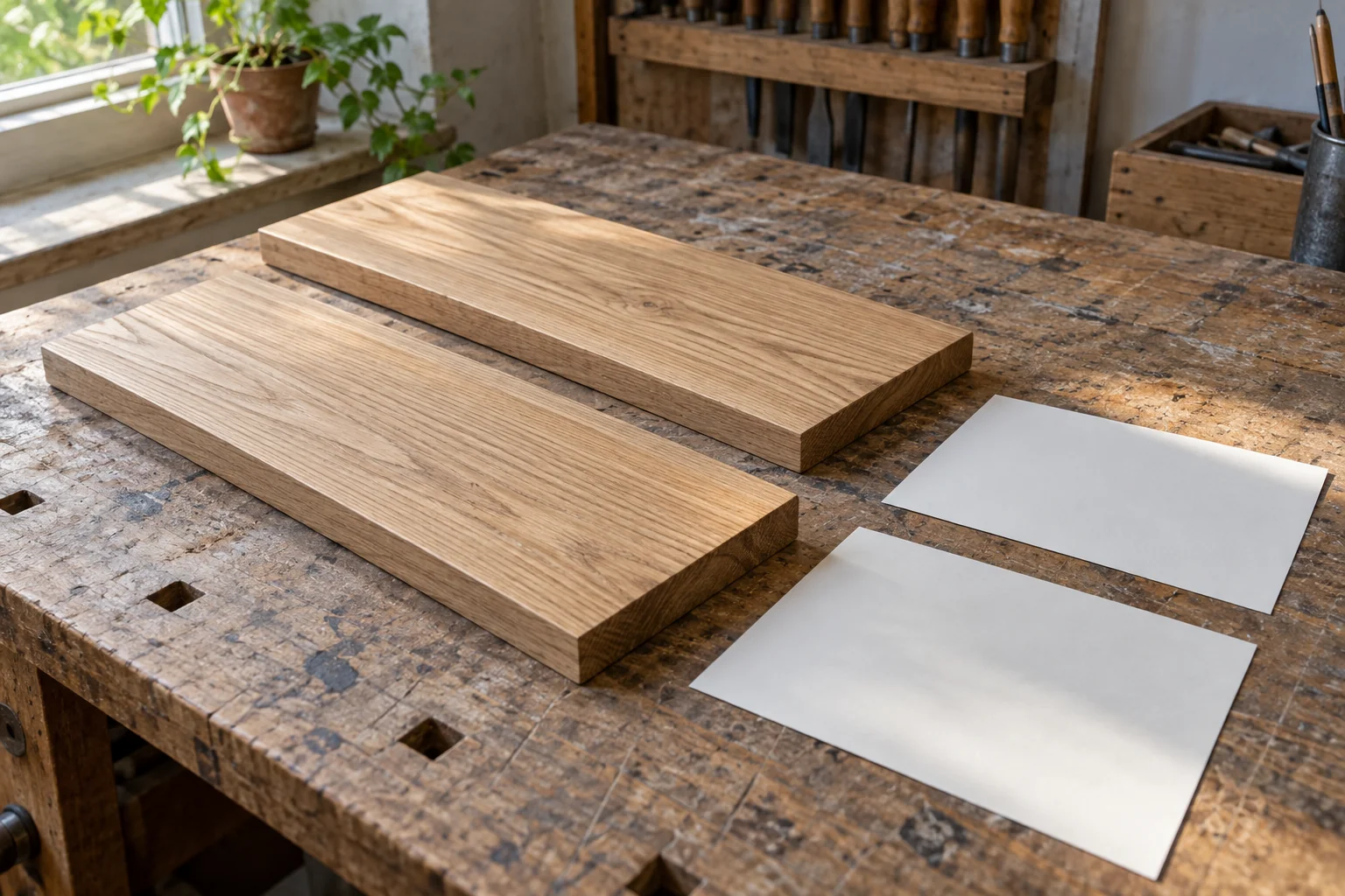
Plan grain direction by marking the intended orientation on each part of your project drawing before arranging the parts on a board. A rectangle that fits after a quarter-turn is not necessarily an interchangeable part: its visible pattern, relationship to neighboring pieces and role in the design may change. Keep the plan’s required orientation separate from your preference for appearance.
Use two different kinds of direction
Start by distinguishing the board from the finished object. A board has faces, edges and ends; the project has a front, back, top and bottom. Those names can describe different surfaces once a piece is assembled. Label the intended visible face and the project’s top on a paper part template so turning it over does not silently reverse the plan.
WOOD’s Board Basics explains that conventional board dimensions relate width across the grain and length along it, and warns that stock and project-part directions can differ. The practical lesson is to preserve both dimensions and orientation. Do not assume that changing their order is merely another way to write the same instruction.
Make a part map before a cutting map
Copy the part names and finished dimensions from the project instructions. Add a line or arrow showing the required grain orientation, with a legend explaining its meaning. At this stage the arrow means the orientation of the wood in the part, not permission to feed a board into a machine in that direction.
Keep machining directions and operations in their own notes, following the tool and project instructions. Grain can be irregular; a decorative surface pattern alone is not a complete guide to a safe cut or a clean planing direction. This worksheet is for planning parts, not prescribing tool technique.
| Part record | Entry | Question to settle |
|---|---|---|
| Identity | Part name and drawing reference | Which piece is this? |
| Dimensions | Thickness and two face dimensions | Which dimension follows the grain? |
| Orientation | Grain arrow and project top | Is rotation allowed by the design? |
| Visibility | Show face and exposed edges | What will the viewer see? |
| Relationship | Neighboring or paired parts | Should the pattern continue or coordinate? |
| Stock assignment | Board identifier and proposed location | Are defects or allowances unresolved? |
Separate required orientation from an optional visual choice
When following a tested project plan, retain its specified material and grain direction unless its designer approves a change. A layout that uses less wood is not automatically a suitable substitute. Where the instructions are unclear, ask before cutting rather than inferring structural suitability from the shape of a piece.
For purely decorative choices within the approved design, compare neighboring faces together. A strong pattern on one side and a quieter pattern on the other may be intentional, but decide while both pieces are still easy to reposition. Mark paired parts as a pair so a later rearrangement does not separate them unnoticed.
A quarter-turn example
Imagine a fictional decorative panel specified as 300 millimeters across by 120 millimeters high, with its grain running across the 300-millimeter dimension. A rectangular opening in your stock layout might accept either orientation. Rotating the part a quarter-turn changes the grain relationship even though the finished outline could still measure 300 by 120.
The worksheet therefore records two facts: the required finished rectangle and the direction of its grain. If the plan requires that orientation, the rotated option is rejected rather than counted as equivalent yield. This is an orientation example, not a claim about the strength of a particular panel or joint.
For two neighboring pieces, also keep a small sketch of their installed positions. A left piece viewed face-up on the bench may need to be turned during assembly. A photograph of the approved arrangement gives you a reference without relying on a vague instruction such as “the pretty side goes out.”
Transfer the map to stock without losing information
Give each board an identifier and note which face is being viewed. Place paper templates over the proposed areas and compare the result with the part map. Keep the project’s cutting and trimming allowances separate from finished dimensions; do not make a tightly packed paper layout that silently leaves no allowance for the actual process.
Use only a marking method appropriate for the material and intended finish. Keep important identification on an approved waste area or a removable paper record when marking the visible face would be undesirable. Do not apply an untested adhesive label to a finished or delicate surface merely to simplify the map.
Check before the irreversible step
Review the part name, dimensions, grain orientation and visible face together before beginning the instructed cutting process. If you change the stock assignment, update the map first. A revised layout is a new decision, even if all of the rectangles still fit.
Save the final map with the project instructions. It records why each piece was oriented that way and makes a later replacement easier to discuss. The useful result is a clear correspondence between board, part and finished object, with appearance choices kept distinct from design requirements and tool-operation instructions.